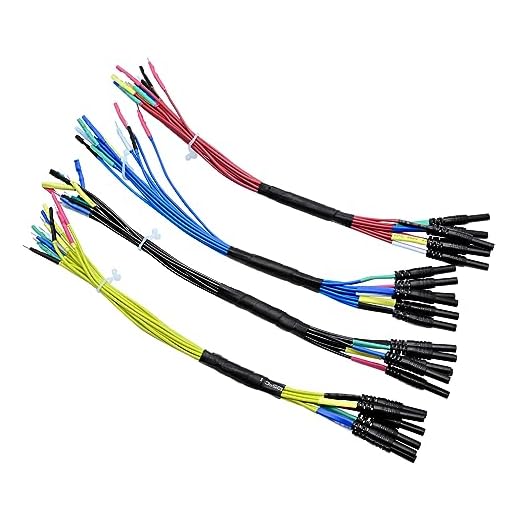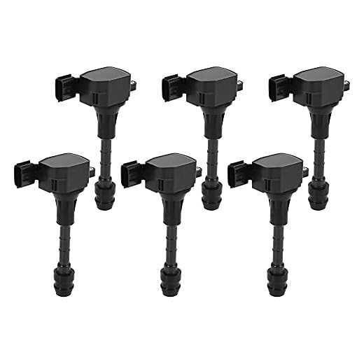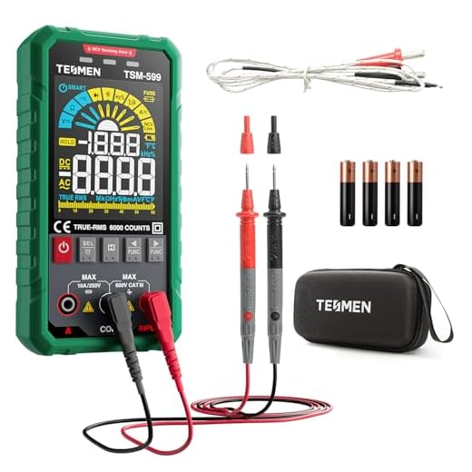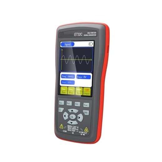


To determine if your cleaning apparatus’s ignition source is functioning properly, employ a multimeter. Set it to measure resistance, then disconnect the wire harness and place the probes across the terminals of the ignition mechanism. A reading between 0.5 and 5 ohms is indicative of a healthy part; anything outside this range suggests a malfunction.
Additionally, inspect for physical damage or corrosion on the connectors. Ensure all connections are secure and free from debris. A visual examination can save time and prevent further issues. Should discrepancies arise during the resistance check, replacing the unit might be necessary for restoring optimal performance.
Consider consulting your equipment’s manual for specific resistance values tailored to your model. Variances can exist between different manufacturers, making it crucial to have model-specific data on hand, enhancing the accuracy of your analysis.
Testing the Spark Generator on a Cleaning Machine
Disconnect the power supply and detach any connected hoses. Locate the spark generator, which is typically found near the engine. Use an ignition tester or a multimeter set to the resistance test function. Connect the tester leads to the output terminal and ground, ensuring a solid connection.
Activate the engine starter briefly while observing the indicator on the tester. A strong, consistent spark indicates proper functionality. If no spark appears, perform a resistance check to verify outputs within the manufacturer’s specifications. Resistance values should generally fall within 3 to 5 ohms; deviations suggest replacement is necessary.
Inspect the connections and wires for signs of wear or damage. Corrosion may impair performance, so cleaning terminals can be beneficial. Ensure all connections are secure before reassembly. Lastly, after replacing or repairing, reassemble the components and perform a trial run to confirm operational stability.
For ongoing maintenance, consider a routine inspection every few months. Catching issues early can save time and cost in the long run.
Identifying Signs of a Faulty Ignition Component
Monitor for inconsistent engine performance, such as rough idling or stalling. If the motor hesitates or fails to start, it could indicate trouble in the ignition system.
Common Indicators

- Hard starting: Difficulty in initiating the engine may suggest a malfunctioning component.
- Reduced power: Noticeable loss in power during operation often points to ignition issues.
- Backfiring: Unexpected backfires during operation might be a sign of misfiring.
- Increased fuel consumption: An inefficient ignition process can lead to higher fuel usage.
Visual Inspection
- Cracks or damage: Check for visible cracks on the unit that could lead to performance issues.
- Corrosion: Look for signs of rust and corrosion on terminals and connections, which could affect conductivity.
- Carbon build-up: Excessive carbon deposits can hinder proper operation.
Pay attention to these symptoms during routine use. Early detection can prevent further damage and costly repairs.
Tools Required for Testing the Ignition System
For an accurate evaluation of the ignition mechanism, it’s essential to gather specific tools. A multimeter is a fundamental instrument, allowing for the measurement of voltage and resistance. This helps in determining if the primary and secondary windings are functioning correctly.
Spark Tester

A spark tester is crucial for checking the output of the ignition system. This device connects to the spark plug lead to visualise the spark during cranking, confirming if the system generates a sufficient electrical arc.
Socket Wrench Set
A socket wrench set is important for removing and reinstalling various components, including the spark plug. Ensure you have the appropriate sizes to avoid damaging any parts during disassembly.
Having a clear understanding of these tools and their applications will streamline the process and yield reliable results. Be prepared and organised before diving into the diagnostic steps, as this will enhance the overall efficiency of your assessment.
Steps to Disconnect the Ignition Coil Safely
Before disconnecting the component, ensure the equipment is completely powered down. Follow these precise steps:
- Ensure the power source is unplugged or the battery is removed to eliminate any risk of shock.
- Wear insulated gloves to protect from accidental contact with any charged parts.
- Locate the connector of the assembly, typically situated near the engine. Carefully inspect for any signs of wear or damage.
- Gently release any retaining clips or fasteners securing the connector in place.
- With a steady grip, pull the connector straight out. Avoid twisting or jerking to prevent damage to the pins.
- After removal, store the connector in a safe place to prevent dust accumulation or accidental damage.
- Visually check the condition of the surrounding wires and components for any signs of corrosion or fraying.
By following these systematic steps, disconnection of the assembly can be performed safely and efficiently, allowing for subsequent diagnosis or maintenance without hazards.
Using a Multimeter for Coil Evaluation
Set the multimeter to the resistance (Ω) setting. Connect the red lead to the positive terminal of the component and the black lead to the negative terminal. A reading within the manufacturer’s specified range indicates good condition.
If the multimeter displays an infinite reading, this indicates an open circuit, signifying a defective unit. Alternatively, a significantly lower resistance may indicate a short circuit within the winding.
Next, to verify the secondary winding, detach the high-tension lead from the terminal. Measure the resistance between the terminal and the ground. A proper reading should typically range between 5,000 to 20,000 ohms. A value outside this range could hint at issues.
During measurements, ensure all connections are secure and the leads do not touch each other, as this could result in erroneous readings. It’s essential to conduct tests methodically to avoid confusion.
Once evaluations are complete, record the results for future reference or repairs. Consistent monitoring will aid in maintaining optimal performance and preventing unexpected failures.
Interpreting Multimeter Readings for Ignition Coils

When measuring resistance, aim for readings between 0.5 to 2 ohms for primary windings. Values significantly outside this range indicate issues. For secondary windings, expect readings of 6,000 to 15,000 ohms. Deviations here suggest failure.
Understanding Low Resistance Values
If the primary circuit shows extremely low resistance, it may suggest a short. This condition can lead to overheating and complete failure of the unit. Ensure to check the connections and wires for any visible damage.
Significance of High Resistance Values
Elevated resistance values often indicate a breakdown in the winding insulation. This can prevent proper voltage generation, impacting performance. Confirmation of readings, especially if unexpected, is crucial; repeat tests after checking probe contacts and setup.
Additionally, ensure your multimeter is functioning correctly by testing against a known standard. A faulty meter can lead to incorrect diagnoses. Observing trends in readings across multiple sessions will also help to identify gradual failures.
In conclusion, carefully analysing the numerical data from multimeter readings enables an accurate assessment of the component’s health. This clarity can save time and resources when troubleshooting equipment malfunctions.
Reassembling and Testing the Pressure Washer After Replacement
Secure the newly fitted component to the machine. Ensure all connections align correctly and fasten screws or clips tightly to prevent dislodgment during operation.
Reconnect the spark plug and any electrical leads you may have detached. Double-check for any loose wires that might affect functionality.
Fill the fuel tank with the appropriate gasoline mixture, adhering to manufacturer guidelines. If your unit requires oil, make certain the oil reservoir is filled to the correct level. Use the specified type to prevent damage.
Before starting, inspect all hoses for cracks or leaks. Damaged hoses can lead to performance issues, compromising pressure generation.
Turn the fuel valve on and prime the pump if applicable. This can usually be done by pressing a primer bulb several times until fuel is visible in the fuel lines.
Start the engine and observe for smooth operation. If it hesitates or struggles to run, revisit the assembly process. Check that all components are connected properly.
Once running, allow the machine to idle for a few minutes before engaging the spray trigger. Monitor for any irregular sounds, vibrations, or exhaust issues that suggest improper assembly.
| Observation | Action |
|---|---|
| Engine Does Not Start | Recheck all electrical connections and fuel supply |
| Unusual Noise | Tighten loose screws or check for misaligned components |
| Weak Spray | Inspect hoses for leaks and ensure the new part is securely locked in place |
| Excessive Vibration | Examine mounting points and ensure proper fitment |
After verifying that everything is functioning correctly, perform a test on a small area to ensure satisfactory performance. This allows assessment of efficiency and operational integrity before tackling more extensive tasks.


