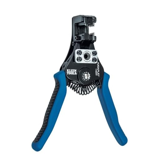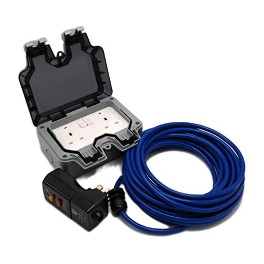


Begin by gathering essential tools: a robust wire stripper, electrical tape, and a suitable connector for secure connections. Ensure the power source is completely disconnected from the unit to avoid any risk of electric shock.
Locate the wiring schematic, usually found within the user manual or on the machine itself. This will guide the connection points between the motor and the power supply. Inspect existing wires for any signs of wear or damage; replace them if necessary to maintain optimal functionality.
Strip the ends of the wires carefully, ensuring there’s enough exposed length for a solid connection. Connect the live, neutral, and earth wires according to the schematic. Secure these connections with electrical tape, ensuring there are no exposed strands that could lead to short circuits.
After connecting everything, double-check each connection. Once verified, reassemble any protective covers. Finally, reconnect power and test the functionality of the unit, monitoring for any unusual sounds or operations.
Connecting a Cleaning Appliance to Its Drive Unit
Start by disconnecting from the mains for safety. Identify the connecting points on the drive unit, typically found near the power input terminal. Ensure that the wires are correctly matched, usually with colour coding: brown for live, blue for neutral, and green/yellow for earth. Strip the ends of the wires to expose copper and insert them into their respective connectors.
Make certain to secure each connection tightly to avoid any accidental disconnections during operation. Use a multimeter to test continuity before powering on the unit. This step is crucial for confirming that the connections are stable and properly established.
Once connections are made, reassemble any covers and ensure the appliance is in its upright position. It’s advisable to check for any leaks before conducting a thorough function test. After powering up, observe the running performance to ensure everything operates smoothly without unusual noises or overheating.
Regular maintenance of connections can prolong service life. Inspect wiring periodically for wear or damage, and replace components as needed to maintain optimal functionality.
Understanding the Wiring Diagram of Karcher Pressure Washers
Examining the schematic is crucial for comprehending the electrical layout. It typically illustrates the connection points for each component including the switch, transformer, and various sensors. Pay close attention to the colour coding of wires; often, manufacturers use specific hues for different functionalities.
Key Components in the Diagram

The wiring diagram encompasses several essential elements:
- Main Switch: Allows for control over the power supply.
- Motor Connections: Indicates terminals where the power line meets the motor.
- Safety Features: Diagrams often include fuses or circuit breakers for protection.
- Grounding: A dedicated line for safety, preventing electrical shock.
Interpreting Connection Types
Wiring diagrams usually represent connections using symbols. Familiarity with these can expedite troubleshooting and maintenance. Solid lines typically depict electrical connections, while dashed lines may denote control circuits.
| Symbol | Description |
|---|---|
| Line with Circle | Connection point for power supply |
| Arrow | Flow of electricity |
| Square | Motor unit |
| Triangle | Transformer or control device |
Understanding these symbols will enhance your ability to perform repairs and modifications safely. Ensure you always refer to the specific schematic for your model, as variations exist between different versions.
Gathering Necessary Tools and Materials for Wiring
Prepare a screwdriver set, including flathead and Phillips types, to handle various screws you encounter. A pair of wire strippers will allow for precise insulation removal, essential for ensuring solid connections.
Obtain electrical tape to securely insulate exposed wires and prevent shorts. Additionally, use heat shrink tubing for a more durable and weather-resistant seal around connections.
Have a multimeter on hand to test voltage and continuity, confirming safe and effective connections before powering the unit. This tool is vital for troubleshooting any electrical issues that may arise.
Acquire suitable wire connectors, such as butt connectors or spade terminals, ensuring compatibility with the wire gauge; these facilitate easy and reliable connections.
Finally, consider a work surface that provides ample space for assembly and testing, along with adequate lighting to maintain visibility while you complete the task. Being well-equipped reduces risk and enhances efficiency during the installation process.
Identifying the Motor Terminals and Power Supply Connections
Find the terminal block located on the motor. It’s essential to correctly identify the input terminals where the power will connect. You will typically see three main terminals:
- L1 – Often represented as a connection point for a live wire.
- N – This is the neutral terminal, usually connected to the neutral wire.
- Ground (E) – Identified by a grounding symbol, it is crucial for safety.
Use a multimeter to verify continuity between the terminals and ascertain proper connectivity. Ensure the supply is disconnected during this process to avoid any electrical hazards.
Next, locate the specifications on the unit’s data plate. It provides important information about voltage and current ratings necessary for proper operations, preventing potential damage:
- Check the voltage rating; commonly, this will be either 120V or 240V.
- Inspect the amperage rating which indicates the current capacity; compliance with these values is critical.
Once confirmed, trace the wires leading to the terminal block. They should correspond to your supply configuration:
- Live wires will usually be coloured brown or black.
- Neutral wires are often blue or white.
- Ground wires are usually green or green/yellow striped.
When setting up the components, ensure that all connections are tight and secure. Loose connections can lead to electrical faults or inefficient operation.
Finally, recheck the entire setup using the multimeter before connecting to power supply. This step is vital to ensure safety and functionality. With the correct terminals identified and established, the subsequent connections can now be made with confidence.
Disconnecting the Equipment from the Power Source Safely

Ensure the unit is fully powered down by unplugging it from the electrical outlet before proceeding. Do not rely solely on the power switch; this may not completely disconnect the device from the electrical source.
After unplugging, verify that any residual power has dissipated. Press the trigger on the gun to release any built-up pressure within the system. This step is crucial to avoid sudden sprays that could cause injury or damage.
Inspect the power cord for any signs of wear or damage. If present, replace it before reconnecting to prevent electrical hazards.
Follow standard electrical safety protocols, including wearing insulated gloves and using non-conductive tools to further ensure safety during the task.
Consider using a circuit tester to confirm that the outlet is not live before you begin working on the internal components. This precaution cannot be overstated; electrical shocks can be extremely dangerous.
Connecting Wires: Step-by-Step Instructions
Begin by stripping approximately 1 cm of insulation from each wire end to ensure a clean connection. Use a wire stripper for precision, which prevents damaging the strands. Ensure that all strands are tangle-free before securing them.
Assembling Connections
Twist the exposed ends of the wires together for a solid mechanical connection. If available, use heat-shrink tubing to encase the twisted section; this provides added durability and prevents moisture ingress. For a more permanent solution, soldering the joints can enhance continuity. Ensure that soldered areas are well insulated with electrical tape.
Attaching to Terminals
Securely fasten the assembled connections to their respective terminals. Ensure that the positive and negative terminals are correctly identified – typical colour codes include red for positive and black for negative. Tighten terminal screws firmly, avoiding over-tightening to prevent damage. After connecting, double-check all connections for firmness and accuracy.
Finally, reconnect any protective covers to prevent accidental exposure, ensuring all components are neatly arranged for safety. Always perform a test run to validate your connections, observing for any unusual sounds or leaks that may indicate an issue.
Testing the Connections Before Reassembly
Ensure all joints are secure before putting the unit back together. Start by using a multimeter to check continuity across all connections. This confirms that the electrical path is intact and that there are no short circuits.
Next, inspect insulation on wires for any signs of wear or damage. Frayed wires can lead to malfunctions or safety hazards. If damage is found, replace the wire sections before proceeding.
After securing physical connections, power the system in a controlled environment before complete reassembly. Look for any unusual sounds or signs of overheating during this initial test. These indicators can show whether the assembly is functioning correctly.
If available, consult the manufacturer’s specifications for voltage readings. Compare the actual readings from your tester to ensure they match the expected values. Discrepancies might indicate an improper connection or component failure.
Remember to perform these checks methodically. Taking the time to validate connections now can prevent future issues and enhance reliability during operation.
Common Issues and Troubleshooting During Wiring
It’s critical to address potential complications that may arise during the setup phase. One frequent issue is reversed polarity, which can cause the unit to malfunction or not power on at all. To prevent this, double-check wire connections against the schematic.
Frequent Problems
- No power: Verify that the power supply is functional and connections are secure.
- Overheating: An incorrect connection may lead to overheating. Ensure terminals are not short-circuited.
- Unusual noises: Check for loose connections or damaged wires, as vibrations can cause noise.
Troubleshooting Steps

- Examine all connections for tightness and corrosion.
- Test power at the source to ensure proper voltage.
- Utilise a multimeter to check continuity throughout the circuit.
- Inspect for damaged insulation on wires, which can cause shorts.
Be methodical in your approach, performing checks systematically to identify issues effectively. Document any findings, as this can aid in future repairs or modifications.


